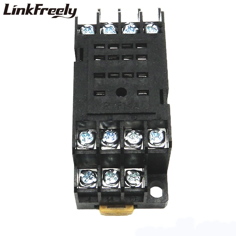
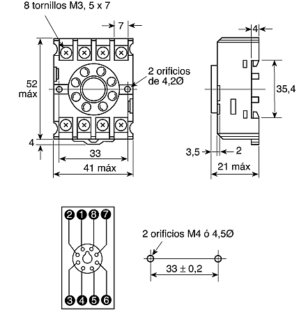
Pin Relay Base Wiring Diagram
Pin Relay Base Wiring Diagram. star delta timer connection In this video I practically explained the time relay. If a large enough positive current is now driven into the Base to saturate the NPN transistor, the current flowing from Base to Emitter (B to E) controls the larger.

Wiring a Denso relay is extremely simple.
Use Relay Location and Electrical Wiring Routing sections to find each part, junction block and wiring harness Numbers outside connector codes indicate the pin numbers of both male and female connectors.
Relay explained, How to use a relay. Single Pole Single Throw (SPST) Relay Wiring Diagram. Typical output signal circuit is shown in the following diagram: Servo drive.


0 Response to "Pin Relay Base Wiring Diagram"
Posting Komentar