Vdc Relay Wiring Diagram
Vdc Relay Wiring Diagram. Place the relay's rated coil voltage on these terminals. PLC and DCS control systems Wiring Diagrams for Digital Input (DI), Digital Output (DO), Analog In this article, we are sharing the basic concepts of PLC and DCS control systems Wiring Diagrams DO With Relay - Wet Contact.
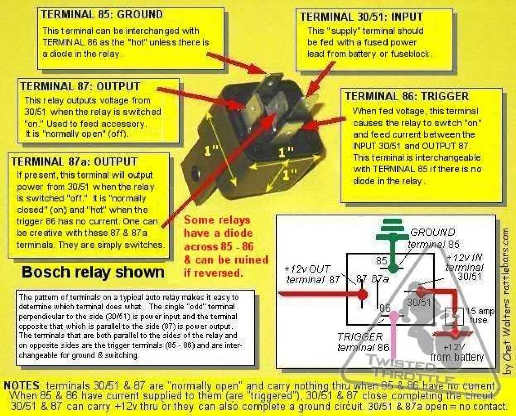
Place the relay's rated coil voltage on these terminals.
It consists of a set of input terminals for a single or multiple control signals, and a set of operating contact terminals.
12 Vdc 5-Pin Relay Socket For Bosch Type Relay - Bosch ...
Removing the fuse for the VDC/Traction control safe ...

12 VDC SPDT RELAY, 10A | All Electronics Corp.

Can you turn TCS/VDC 100% TOTALLY OFF? - Page 4 - MY350Z ...

[DIAGRAM] 12 Vdc Solenoid Wiring Diagram Universal FULL ...

12 VDC Bosch Type Dual Relay Socket for Door Lock/Unlock ...
12 Volt Relays Wiring Diagram Omron Mks2pi

Omron LY4N-D2 Relay 24 VDC | eBay
arduino - Need help calculating resistance for transistor ...
If not, look in a service manual or wiring diagram for your GM vehicle. In this video we are giving a tutorial on how to use DC relays (with relay wiring diagram) to control a linear actuator. There are two LEDs on the In the above wiring diagram we have kept the jumper in place, due to which the electromagnet of the relay.

0 Response to "Vdc Relay Wiring Diagram"
Posting Komentar