Pin Connector Diagram
Pin Connector Diagram. It appears that you are using AdBlocking software. An electrical connector is an electromechanical device used to join electrical conductors and create an electrical circuit.

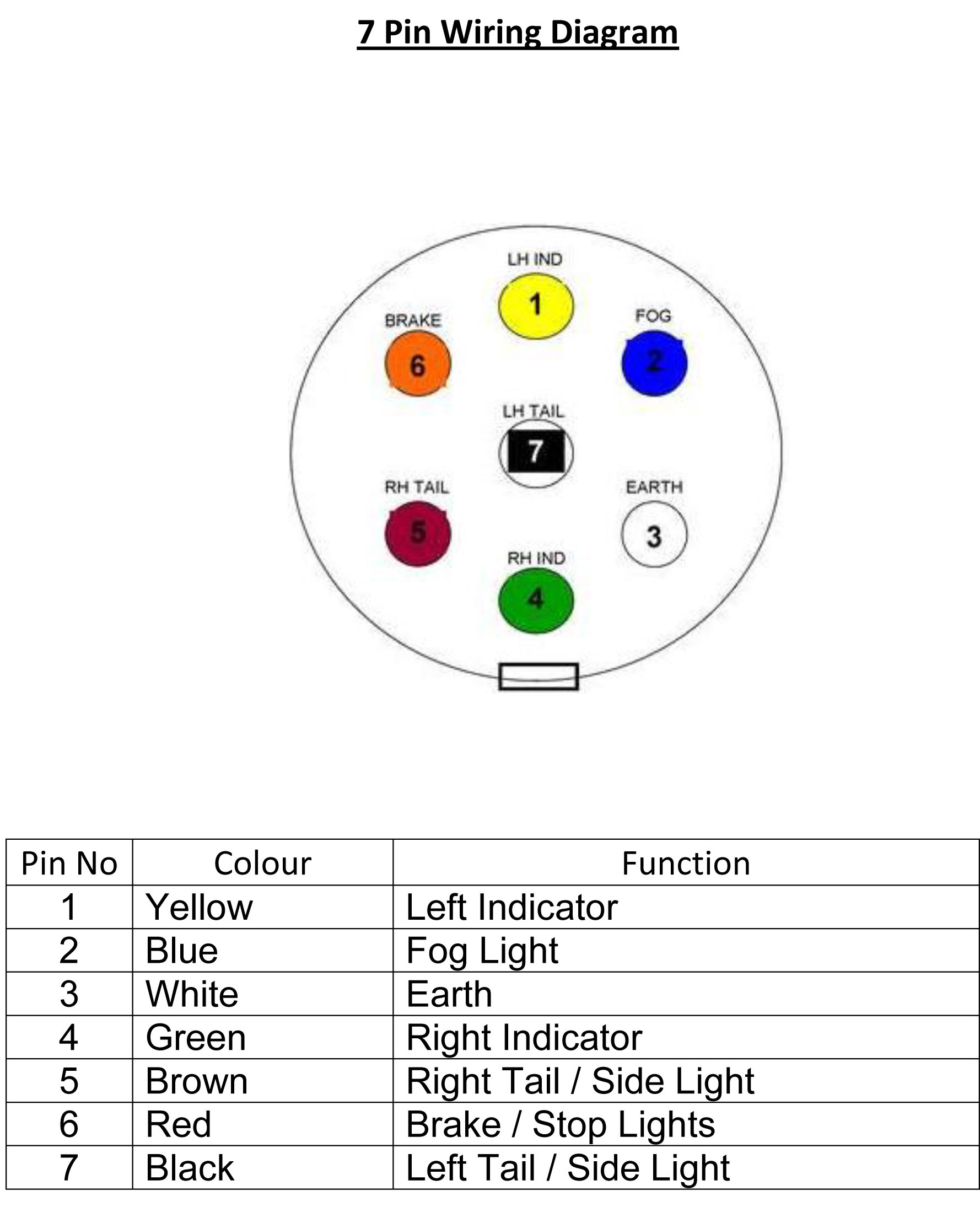
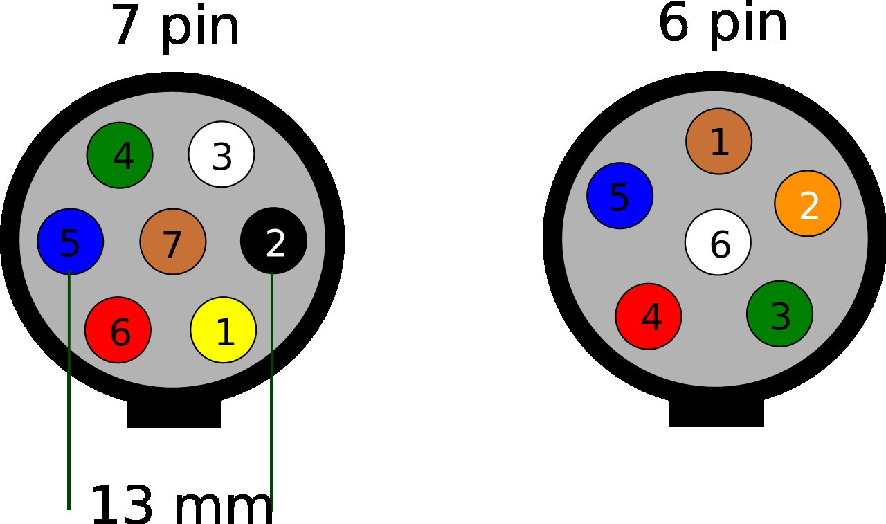
This diagram represents a top-down view looking directly into the connector.
Connectors can be either pinned temporarily or pinned permanently.
7 pin wiring diagram - Ford F150 Forum - Community of Ford ...

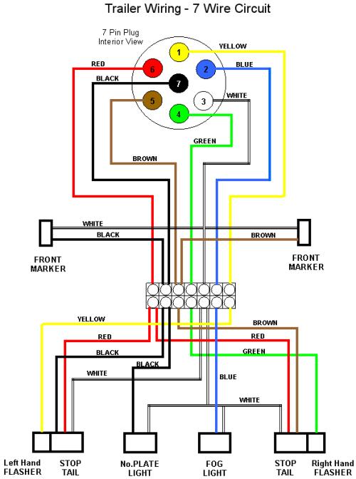
7 Pin Trailer Wiring Diagram Nz | Trailer Wiring Diagram
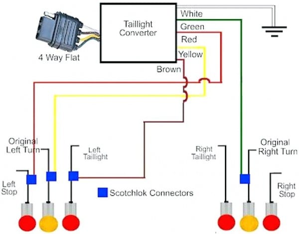
4 Pin Trailer Connector Diagram
Diagrams & Technical Information | Edwards Trailers

EXP GDC HDMI-to-mPCIe wiring diagram | Expresscard, mPCIe ...
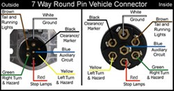
Wiring Diagram for 7-Way Round Pin Trailer and Vehicle ...

Wiring Diagram For 7 Pin Trailer Connector | Trailer ...
Trailer Wiring Diagram 7 Pin Round | Wiring Diagram

7 Pole Round Pin Trailer Wiring Connector Diagram ...
They are often used for testing electrical signals on printed. Connectors can be joined at the same point of a shape on the diagram. Most electrical connectors have a gender - i.e. the male component, called a plug, connects to the female component, or socket.

0 Response to "Pin Connector Diagram"
Posting Komentar