Pin Rgb Cable Wiring Diagram For
Pin Rgb Cable Wiring Diagram For. If you plug an IDC-cable into your RGB panel to the input connector, this is how the signal positions are on the other end of the cable (imagine the Wiring diagram. Wiring Inside Diagram On Vga To Hdmi Wiring Diagram - Wiring Diagram - floraoflangkawi.org.
![Buy Lian Li Strimer 8 Pin RGB Cable [STRIMER-8] | PC Case ...](https://files.pccasegear.com/UserFiles/STRIMER-8-f_01.jpg)
The following diagrams in this note used NPN transistors had pins from the left that were.
The longer the cable is the more capacitance between the wire.

Pana Twin MP-92 RGB pinout - Arcade Otaku - アーケード オタク
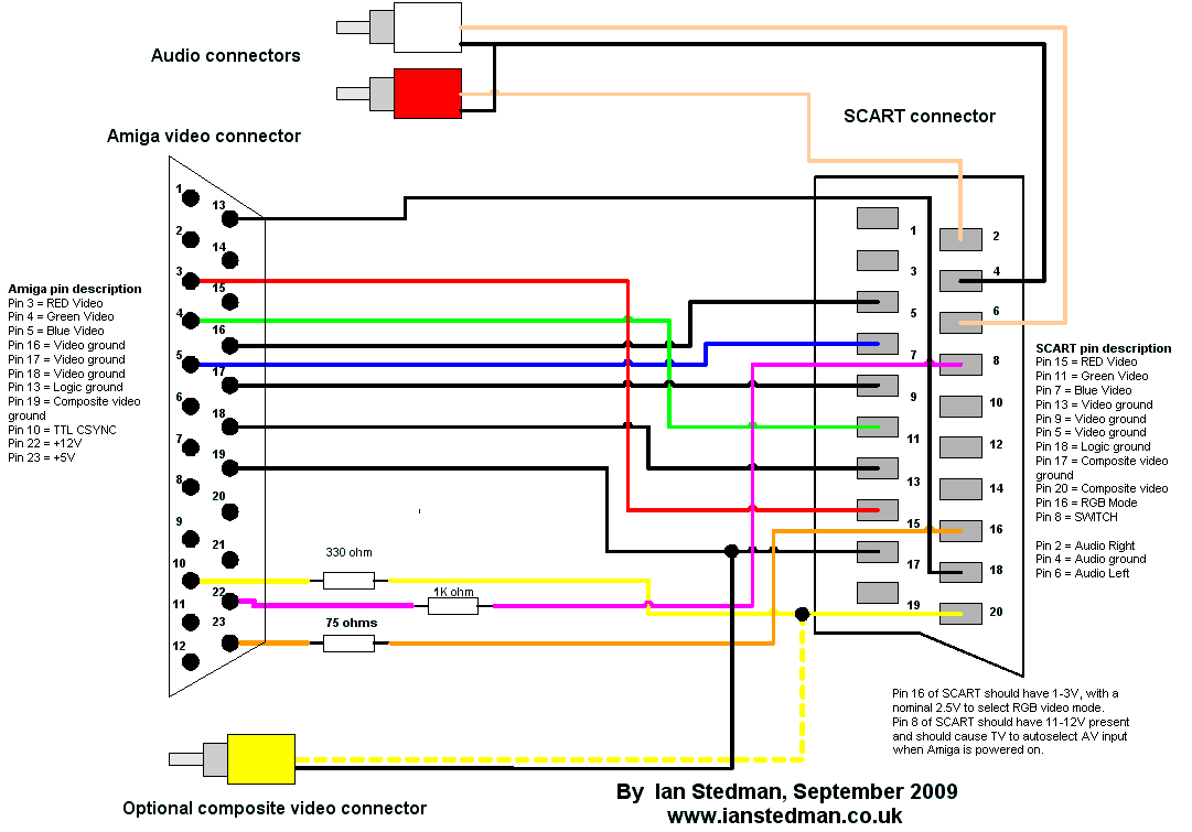
No audio on one SCART cable,another cable is fine ...

rgb led strip connector for 4 Pin 5050 LED Strip Lights ...

CGA RGB DB9 to HD 15-pin VGA Adapter Cable
SCART RGB interfacing

1084S RGB Scart Adapter - Home Computer & PC - Circuit-Board

Buy online VGA to RGB RCA Cable in Ireland
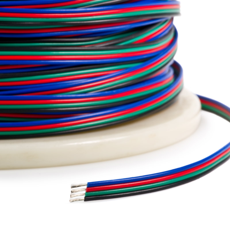
22 Gauge Wire - Four Conductor RGB Power Wire, | Power ...
BIFI 5M 4 Pin RGB LED Extension Wire Connector Cable Cord ...
We have so many standards out there, that it really can defeat the purpose of the whole thing. However, you can change their 'Color changing time' applying PWM to it's Vcc pin. Here is a wiring diagram and pin out: Modular Connector Plug and Jack Pin Out.

0 Response to "Pin Rgb Cable Wiring Diagram For"
Posting Komentar